
Transmitting QPSK Signals
Objective
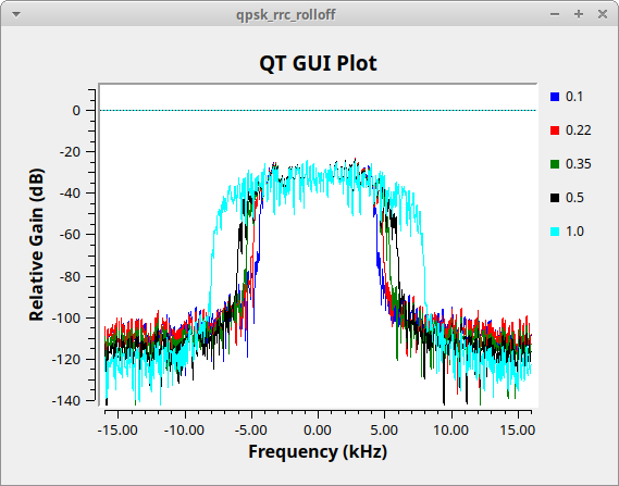
This step is mainly to generate QPSK signals randomly and observe the effect of different Excess BW parameters on the signal bandwidth.
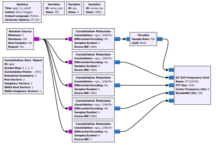
System architecture file: Qpsk_rrc_rolloff.grc
Steps and Instructions
- First, generate a random bit stream.
- Random numbers 0~255 are equivalent to 8 bits.
- The output is unpacked char type.
- Use
Constellation Modulatorto generate QPSK signals.Constellation ModulatorusesConstellation Rect. Objectto map symbols 0, 1, 2, 3 to signal points on the complex plane.- Differential Encoding is set to Yes, which means differential encoding is used, that is, the phase difference between the current input and the previous output.
- Samples/Symbol is set to 4, which means each symbol is repeated 4 times.
- Excess BW is the alpha value of Root Raised Consine, which is generally set between 0 and 1, mainly used to control bandwidth. Raised Consine Filter is often used to deal with waveform and ISI problems. Root Raised Consine is the square root of Raised Consine.
System Simulation
Additional Notes
Raised Cosine and ISI Relationship
In digital communication systems, in order to avoid inter-symbol interference (ISI), Raised Cosine Filter is often used as a pulse shaping filter. Raised Cosine Filter is a common type of filter with the following characteristics:
- In the time domain, the Raised Cosine pulse is zero at the symbol sampling point, which can effectively eliminate ISI.
- In the frequency domain, the Raised Cosine filter has a flat passband and a steep cutoff characteristic, which can limit the signal bandwidth.
When both the transmitter and receiver use Root Raised Cosine Filter, the overall system impulse response is equivalent to a Raised Cosine Filter, which is a Nyquist filter that can perfectly recover the original signal and eliminate inter-symbol interference.
Significance of Excess BW
Excess BW (Bandwidth) refers to the alpha (or roll-off factor) parameter of the Raised Cosine Filter, which determines the transition bandwidth of the filter. The value of Excess BW is usually between 0 and 1, and has the following meaning:
- When Excess BW is 0, the Raised Cosine Filter degenerates into an ideal rectangular filter, and the bandwidth of the filter is equal to half the symbol rate. However, ideal rectangular filters are difficult to implement in practice.
- When Excess BW is 1, the Raised Cosine Filter has the widest transition band, and the bandwidth of the filter is twice the symbol rate.
- When Excess BW is between 0 and 1, the transition bandwidth of the filter is between the above two cases. A larger Excess BW value will result in a wider transition band and higher bandwidth utilization, but it will also introduce more ISI.
Choosing the appropriate Excess BW value requires a trade-off between bandwidth utilization and ISI suppression. Typically, a typical value for Excess BW is 0.35 or 0.5, which can provide good compromise performance.
Differential Encoding
Differential encoding is a commonly used encoding technique, especially suitable for coherent demodulation communication systems such as QPSK, QAM, etc. The main purpose of differential encoding is to eliminate the phase ambiguity problem in the demodulation process and improve the reliability of the system.
In differential encoding, the transmitted symbol is not directly mapped from the input data, but is obtained from the phase difference between the current input data and the previous transmitted symbol. At the receiver, the demodulator does not need to estimate the absolute phase, but recovers the original data by comparing the phase difference between adjacent received symbols. This eliminates the phase ambiguity problem caused by phase offsets introduced by the channel.
Exercise 1
Query the Raised Consine function, observe the graphs of different alpha values, and compare them with the simulation results.